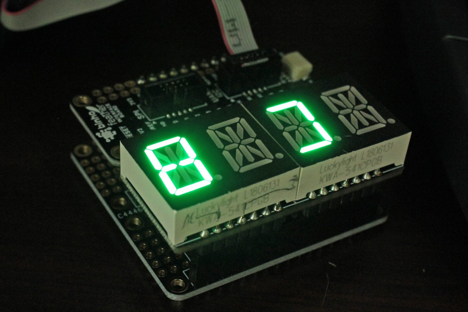
After doing an initial review of the binho host adapter device on Hackster.io, my next task was to test it out in a “real world” usage scenario. In this case it meant experimenting with the Adafruit .54” Quad Alphanumeric FeatherWing display. The display communicates with the world via I2C, and in my opinion represents one of the most interesting use cases for the Binho USB Host adapter: sending I2C (and likely SPI) signals directly.
In other words, while it’s easy enough to use I2C via Arduino libraries and the like, actually understanding how things work is generally kept behind the scenes. If you want to dive deeper, the binho device will allow you to input I2C commands on the binary/hex level. Once you’ve mastered that, you can plug in an I2C device and check out its functionality directly, without being held back by the constraints of a particular library. Pretty neat.
Initial Experiment
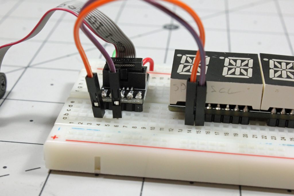
For initial experimentation, the Adafruit device was hooked up on a breadboard, with I00 on the included adapter controlling the SDA line and, I02 attached to SCL. The Binho 5V bus and ground were used to power the FeatherWing.
Actually controlling the device with your own independent I2C device is something of a reverse engineering challenge, and mostly comes down to examining the ht16k33 library that controls it, along with the HT16K33 datasheet. Admittedly, I had a bit of assistance from binho, but did have the “magical” binary combinations seen below written out on my bulletin board by the time they sent the info over.
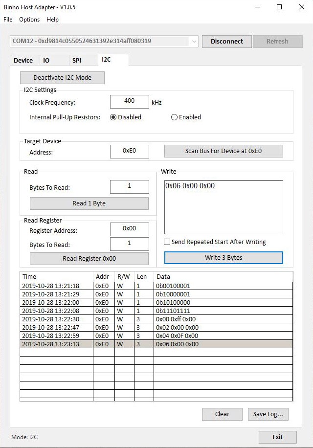
The long and short of it is to begin with you’ll need to first scan the bus and target what you find on the GUI to communicate with the correct I2C device. Note that the device I’m using is listed by Adafruit as a 7-bit I2C address, while the Binho GUI expects an 8-bit. Scanning the bus will take care of this, but it may be different than you expect. I also had to toggle the pullup resistors to get things to work, but it seems this may be a glitch in the (very early revision) software that will be corrected. I then sent a couple commands to your ‘Wing to set things up:
- 0b00100001 Wake up, note that “0b” indicates a binary number
- 0b10000001 Turn on the display with no blinking
- 0b10100000 Correctly setup output pins
- 0b11101111 Set brightness to maximum
Alternatively, you can send these commands as the hex equivalents: 0x21, 0x81, 0xA0, and 0xEF.
With that done, you can turn individual segments on and off using binary or hex as you so desire. Each character is represented by 16 bits, corresponding to segments and a period between digits, and you need to enter a 1 for each segment you want on, 0 for those that need to be off. The first byte indicates the digit (0x00, 0x02, 0x04, 0x06 as each segment information is two bytes long). So 0x00 0b00000000 0b00000000 turns the first segment entirely off, which can also be expressed as 0x00 0x00 0x00 in all hex if you so prefer.
Looking at Adafruit’s LED backpack library, lines 88 through 181 shows how to construct a number of different characters in binary. Note here that information is entered least-significant bit first, so for instance the character 8, listed as: 0b0000000011111111, would be entered into the binho GUI as 0x00 0b11111111 0b00000000. Or this can also be expressed as 0x00 0xff 0x00 (0b and 0x indicating binary or hex numbers here), which is much easier to enter.
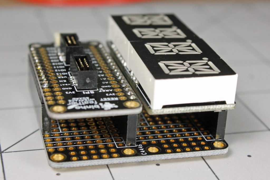
FeatherWing Doubler
For a better looking setup with this type of product, binho also offers an adapter in the same form factor as the Adafruit FeatherWing series. In my case I just used Adafruit’s doubler product, which allowed me to plug in the binho adapter without any sort of extra jumper wiring. The connections are already lined up as far as data, power, clock and ground, so other than soldering the headers correctly and plugging everything in, there’s not much to worry about.
Once you’re done with Binho experimentation, an actual Adafruit dev board could be plugged in instead of the adapter board, allowing you to continue with whatever project you had in mind. Alternatively, you could test out other devices without the need for more soldering.
Going Further?
Using this adapter has been a fun learning experience for me, delving further into the I2C protocol, and experimenting with number formatting and reverse engineering. At $150, it’s not as cheap as hooking up an Arduino to just run whatever it is you’d like to power, but I can see this adapter being extremely useful in the following applications:
- A really excellent hands-on educational tool for I2C, as well as SPI, and general IO functions. I’ve learned a lot experimenting with it, and it could be used in a number of hands-on exercises. This could be useful to students new to physical computing altogether, to more advanced learners who are getting their hands around different protocol concepts.
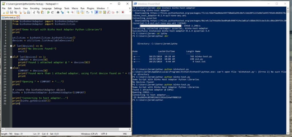
- Low-run testing and QA device. As it just so happens the binho host adapter is extremely capable of going through a variety of automated routines via its Python library. I plan to do some experimentation with this in an upcoming post, so be sure to check back later to see how this develops!
- Advanced reverse engineering adapter. For instance if you’re trying to revive a display from the early 1980s or similar, having a direct link through the adapter rather than going through an ad hoc middleman (Arduino or otherwise) could make things much easier.
If you want to try out this product yourself, the adapter is available here, along with software and a number of accessories to go along with it.
*Note that this article was paid for by Binho. That being said, it’s a really interesting product, and I’d certainly recommend the device if it fits your needs.
This article appeared on JCoPro.net in 2019, and can also be found on Medium.